Jane Medium : This paper gives MicroPython Kernel Development Notes : Experimental tasks are embedded in the book About SCM port software use case part of the content .
key word: Input and output ,MicroPython,Pin,MM32F3277
Software use case : PIN Basic port input and output functions provided by the module .
This part of the manuscript includes :
- Output experiment :
- Input experiments :
- Position in manuscript :
Using modules Pin The single-chip computer can be IO The port is configured to input 、 Output 、 Additional functions and other modes . The basic syntax is :
led = Pin('PB2', mode=Pin.OUT_PUSHPULL)
The above statement will PB2 The pins are configured as push-pull output pins , And defined as a variable led . among Pin The first parameter of is the singlechip pin naming string , The second parameter is pin mode . Pin output modes that can be used include :
【 surface 1-1 Pin mode column table 】There are several ways to set the high and low levels of output pins , With led Port as an example .
There are several ways to read the port logic level , With led Port as an example .
key = Pin("PC1", Pin.IN_PULLUP)
print(key.value())
print(key())
Single chip microcomputer IO Port drive external LED There are two patterns :
In the following experiment, the output current driving mode is used to complete the external LED drive .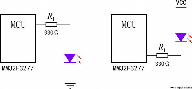
▲ chart 1.1.1 Single chip drive LED Two modes Left : Output current drive mode ; Right : Input current drive mode utilize Pin Control the high and low level of single chip microcomputer pin , Drive external LED flashing . The experimental hardware platform is Simple experimental board , among PB2 Connect external LED. High level lighting , Low level off .
The experimental software code is as follows :
from machine import Pin
def delay(loop=10000):
for _ in range(loop):
pass
led = Pin('PB2', mode=Pin.OUT_PUSHPULL)
print('Test LED.')
while True:
led(1)
delay(50000)
led(0)
delay(50000)
In software , First of all, will PB2 Defined as Output pins , The mode is push-pull output . When it is high , The output current can be turned on LED. Pin output includes two modes :
It is driven by output current LED, Can only choose PUSHPULL Pattern ; It is driven by input current LED, Then the above two modes can be used .
Please note that , In this software example , Write the delay Implement software delay . At the back of this book , The internal timer module will be introduced time, future delay Subroutines can use time Module sleep Related functions replace .

▲ chart 1.1.2 LED Flashing operation The purpose of this experiment is to show that the output pins of single chip microcomputer are configured into two different output modes ( Push pull mode and open drain mode ) The difference between . MCU output pin is at low level , Both modes can absorb current from the outside ; The output pin of single chip microcomputer is high level , Push pull mode can output current , However, the open drain mode is equivalent to the high resistance state .
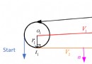
In special circumstances , Single chip microcomputer is required One IO Two ports can be controlled independently at the same time LED The state of . The following experiment is to use LED And the threshold characteristic of the conduction voltage IO Two ports are controlled independently LED state . The schematic diagram of the experimental circuit is as follows :
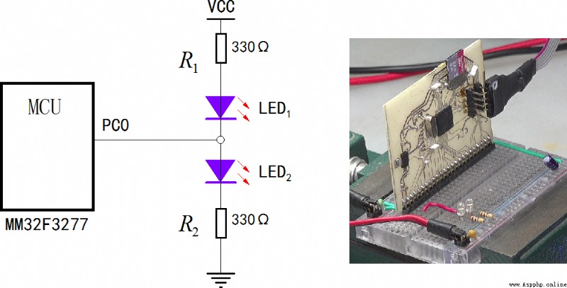
▲ chart 1.1.3 Single IO Mouth control two LED Experimental circuit Two used in the circuit LED It's white or blue LED, Their lighting voltage exceeds 2.5V, So the voltage of single-chip microcomputer VCC=3.3V Not enough to directly drive two in series LED . When the output of single chip microcomputer is high resistance , Two LED db Extinguish ; When the MCU pin output is low ,LED1 Lighten up ; When the pin output of the single chip microcomputer is at high level, it is ,LED2 Lighten up ; When the MCU pins alternately output high at a higher frequency 、 When the electricity is low ,LED1、LED2 Will be lit at the same time .
from machine import Pin
import time
led = Pin("PC0", mode=Pin.OUT_OPENDRAIN)
led(1)
ledstatus = 0
def ledout(status):
global led
if status == 0:
led = Pin("PC0", mode=Pin.OUT_OPENDRAIN)
led(1)
else:
led = Pin("PC0", mode=Pin.OUT_PUSHPULL)
if status == 1:
led(1)
elif status == 2:
led(0)
else:
led(1-led())
print("Test two LEDs.")
count = 0
while True:
ledout(ledstatus)
count += 1
if count >= 200:
count = 0
ledstatus += 1
if ledstatus >= 4: ledstatus = 0
time.sleep_ms(5)
In the above procedure , The main loop program uses time.sleep_ms Function to delay , every other 5ms By function ledout changes LED Control port led Settings and status of . stay ledout Function , According to input status Value 0,1,2,3, Set separately led by High impedance output 、 High level 、 Low level and state switching .
In the main cycle , every other 1 Second pair led State in 0、1、2、3 Switch between , For the external two LED Then they are at Total destruction 、LED1 bright 、LED2 bright 、 Fully lit .

▲ chart 1.1.4 Single IO Mouth control two LED Light up separately Select single-chip microcomputer PC1 Set as key input port , Use its state control LED The light of the sun .
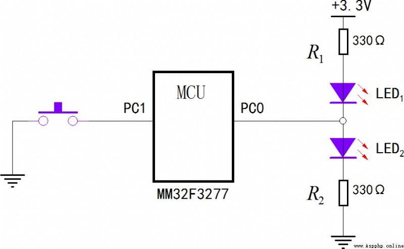
▲ chart 1.2.1 Use the input port to control LED state The experimental code is as follows :
from machine import Pin
led = Pin("PC0", Pin.OUT_PUSHPULL)
key = Pin("PC1", Pin.IN_PULLUP)
while True:
led(key())
Use input port directly key() Get input port status , Change its value led Output level . Because the input port is grounded through the key , So in initialization key When , The input mode with pull-up resistor is used .

▲ chart 1.2.2 Change... By pressing the key LED The state of Single chip microcomputer MM32F3277 Pin as IO Input port , The input characteristic is equivalent to a comparator , The threshold value of the comparator is half of the operating voltage (3.3/2 = 1.65V). When the input voltage is greater than the threshold , The input logic level is 1, When the input voltage is less than the threshold , The input logic is 0 .
The programmable digital DC voltage is applied to the input port of the single chip microcomputer PC1, Still run the above key program , take PC1 The input logic level passes PC0 Output . The circuit diagram for measuring the voltage characteristics of the input port is shown in the figure below .
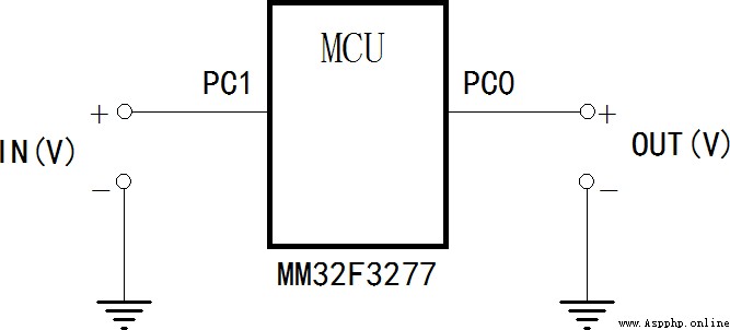
▲ chart 1.2.3 Test the voltage characteristics of the input port Use a multimeter to measure the relationship between input voltage and output level , As shown in the figure below . It can be seen that when the input port voltage is greater than 1.65V when , The output is high level ; Less than 1.65V when , The output is low level .
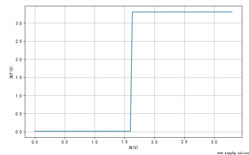
▲ chart 1.2.4 Input voltage IN And output voltage Arrange the input port characteristics in the experiments in this chapter , For the next chapter utime In the experiments , Use Pin To measure some physical quantities in preparation .
This paper gives MicroPython Kernel Development Notes : Experimental tasks are embedded in the book About SCM port software use case part of the content .
Now this version , Direct passage through... Is not allowed Pin.mode Yes Pin To modify the properties of . such as :
led = Pin("PC0", mode=Pin.OUT_OPENDRAIN)
Use led.mode = Pin.OUT_OPENDRAIN It's illegal .
It is suggested to add led.mode Directly modifying , It can improve the execution efficiency of the program .

■ Links to related literature :
● Related chart Links :