Jane Medium : This paper gives MicroPython Kernel Development Notes : Experimental tasks are embedded in the book Medium utime Some contents of software use cases .
key word: Software ,MicroPython,MM32F3277,utime,time
Software use case :
This part of the manuscript includes :
- Basic experiments : Interactive view time The basic function of the module ; drive LED flashing ;
- utilize time Measure software execution time , To measure Time interval of port signal .
- Position in manuscript :
By the following command , You can see time Basic functions of .
import time
dir(time)
time.ticks_cpu()
time.ticks_ms()
time.ticks_us()
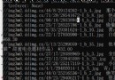
The output of the command is :
['__name__', 'sleep', 'sleep_ms', 'sleep_us', 'ticks_add', 'ticks_cpu', 'ticks_diff', 'ticks_ms', 'ticks_us']
158519
158520
158521000
>>>
You can see from above time The main functions in include :
ticks_cpu And ticks_ms In fact, the output values are the same , ticks_us Is in ticks_ms Just multiply by 1000, That is, this is actually a fake us Time delay , For some time delay measurements that require high accuracy, it will have adverse effects .
utilize time The delay function of , The loop of the main program can be controlled more accurately . This is very important in some occasions where high timing accuracy is required , For example, use the main program PID control , It is required to strictly maintain the set duration of the control cycle . So precise latency is very medium for embedded software development .
The following program uses time Delay implementation external LED flashing .
from machine import Pin
import time
led = Pin("PC0", mode=Pin.OUT_PUSHPULL)
while True:
led(1)
time.sleep_ms(250)
led(0)
time.sleep_ms(250)
The image below shows LED Flashing condition .

▲ chart 1.1.1 time Delay generation LED flashing Right up there LED In the scintillation experiment , Set different... By measuring time.sleep_ms The values correspond to LED Flicker rate , analysis time Delay time accuracy .
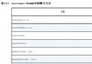
The following is true. time Time delay n The values are respectively from 1 To 25 change , Output LED Square wave frequency value .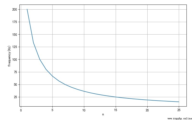
▲ Corresponding to different time Time delay measurement LED Flicker rate By using the function for the above numerical interval 1 / f = 2 a ⋅ ( n + b ) 1/f = 2a \cdot \left( {n + b} \right) 1/f=2a⋅(n+b) Fit , Can be found a,b about 1.25 and 1. therefore , This time can prove , Implemented in this version time Delay in progress , There are systematic errors . about time.sleep_ms(n) sentence , In fact, the delay time is 1.25(n+1) ms.
application time Medium ticks_cpu You can get the time delay between two pieces of code in the program , This feature can Application in ultrasonic measurement 、 Capacitor charging and discharging time, etc , It can also be used to measure MicroPython The time consumed by program execution , This is of great significance in program optimization .
It is a pity that , The current version can only provide ms Level of time resolution . Therefore, if the measurement accuracy is improved , There is also a need to improve the internal implementation mechanism .
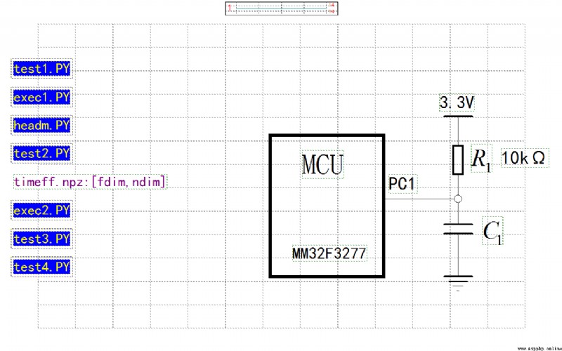
The following applies the single chip microcomputer pin, which can be configured into the input and output mode , And it has comparative characteristics for external input voltage . application RC Charge discharge characteristics can measure unknown capacitance . The measuring circuit is as follows , among R1 Is the known resistance , In the experiment 10kΩ. C1 Is the capacitance to be measured .
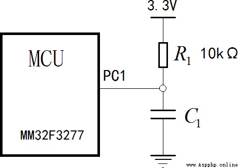
▲ chart 1.3.1 Experimental circuit for measuring capacitance Before measurement , take PC1 Configure to output mode , take C1 The voltage on the is released to 0V about . And then PC1 Set to high impedance input state , 3.3V The power supply will pass through R1 Yes C1 Charge , When the input voltage exceeds the port threshold voltage U 1 U_1 U1 after , PC1 Input logic from 0 become 1, utilize time Of ticks_cpu Function to get the charging time t 1 t_1 t1 . according to RC The charging and discharging laws are known t 1 = R 1 C 1 ⋅ ln ( 3.3 3.3 − U 1 ) t_1 = R_1 C_1 \cdot \ln \left( { { {3.3} \over {3.3 - U_1 }}} \right) t1=R1C1⋅ln(3.3−U13.3)
According to the known R1 The numerical , Then we can calculate to be tested C1 The capacity value of .
Here's the test program .
from machine import Pin
import time
pinc = Pin("PC1", Pin.OUT_OPENDRAIN)
pinc(0)
def measureC():
startc = time.ticks_cpu()
pinc = Pin("PC1", Pin.IN_FLOATING)
time.sleep_ms(1)
while True:
if pinc.value() != 0:
endc = time.ticks_cpu()
break
pinc = Pin("PC1", Pin.OUT_OPENDRAIN)
pinc(0)
return endc - startc
while True:
ret = measureC()
print(ret)
time.sleep_ms(1000)
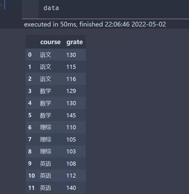
The following is the voltage waveform of the capacitor to be measured . You can see that , The voltage is charged to 1.84V, Corresponding threshold voltage U 1 = 1.84 V U_1 = 1.84V U1=1.84V .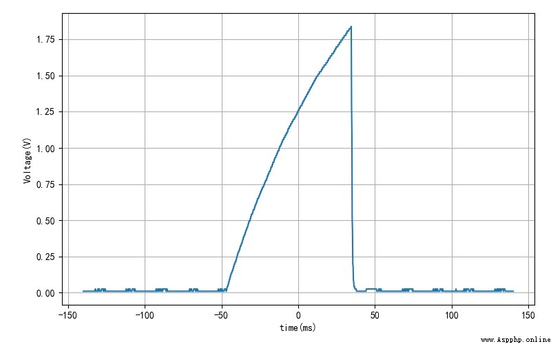
▲ To be tested C1 Voltage waveform on The value returned by the program running is 65. According to the previous delay accuracy measurement , Actual charging time t 1 = 65 × 1.25 = 81.25 m s t_1 = 65 \times 1.25 = 81.25\,ms t1=65×1.25=81.25ms . According to what is known R 1 = 10 k Ω R_1 = 10k\Omega R1=10kΩ , The capacitance to be measured can be obtained
C 1 = 81.25 R 1 ln 3.3 3.3 − U 1 = 9.97 μ F C_1 = { {81.25} \over {R_1 \ln { {3.3} \over {3.3 - U_1 }}}} = 9.97\mu F C1=R1ln3.3−U13.381.25=9.97μF
This value corresponds to the nominal value of the capacitance 10 Micro method Very close to .
This paper gives MicroPython Kernel Development Notes : Experimental tasks are embedded in the book Medium utime Some contents of software use cases .

Through the experiment, we can see , In the migration software version ,time There is a systematic error in the delay time , That is to say, there are some problems in porting software BUG, This is a common mistake that programmers make . According to the current version , time.sleep_ms(n) The actual delay is 1.25(n+1) ms. It is suggested that this part BUG Modify .
stay time.ticks_us(), ticks_cpu() It is better to realize the internal high-precision timer .
■ Links to related literature :
● Related chart Links :