本文已參與「新人創作禮」活動,一起開啟掘金創作之路.
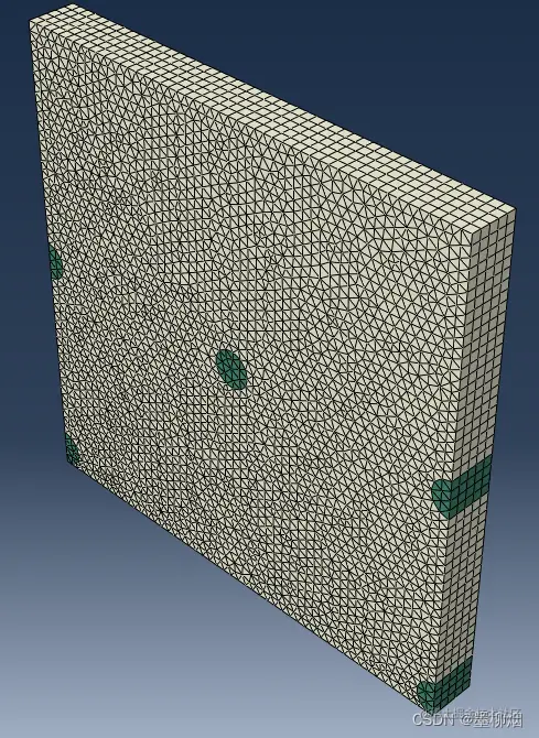
Before following the video tutorials and books, I wrote a small study note:Abaqus-python-Secondary development study notes-Unidirectional long fibersRVE,Only one fiber is drawn,And in the paper,Often consists of a large number of randomly distributed fibersRVE模型,如圖所示,It better reflects the real situation.This note supplements this study.
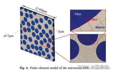
Figure is from the paper The effects of fiber radius and fiber shape deviations and of matrix void content on the strengths and failure mechanisms of UD composites by computational micromechanics
This article is the main reference tutorial:  www.youtube.com/watch?v=UmT…,Found while searching for tutorials,Most composite materialsRVETutorials are published by this blogger,He should be an expert on this,In fact, he has written programs that can be used directly,但是是40Paid software in dollars,For now, it's just a matter of staying away,Still need your own efforts to achieve.
ps.My abilities are limited,Childish thinking and decisions are inevitable,or lack of awareness,Hope you all have a harmonious discussion,給予批評.
觀察上圖的RVE模型,可以看到有很多“切斷”的纖維,其上下、The left and right satisfy the periodicity, respectively.So when generating random fibers,The ordinary randomly distributed fibers in the middle need to be considered,Fibers on the boundary also need to be considered to ensure periodic distribution. Observe that the fibers at the four corners of the figure are only partially present,I am concerned here that it will affect the mesh if the cross-section of the fibers is smaller here in the subsequent meshing,So the code should be considered.針對該問題,I directly avoid generating fibers at the four corners in the subsequent code implementation,The fibers on the four sides also need to meet the condition that the cut part is not too small.
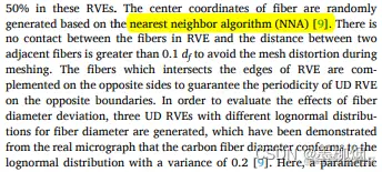 The above paper adopts a method called nearest neighbor algorithm (NNA)algorithm to generate random fibers,The volume content is controlled at50%. This method will be implemented in subsequent studies,For now, I first use a simple method to experiment.
The above steps can be found in python或matlab中實現,Get the center coordinates of the fiber,為列表形式,Take it out in turnabaqusto create fibers. should be considered hereabaqus的代碼實現,先GUI界面進行操作,After observing the code, rewrite it accordingly.
Repeat with previous study article、Unimportant content will be skipped
The protruding part of the fiber that needs to be cut can be seen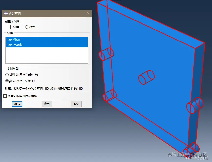 .rpy文件代碼如下
from abaqus import *
from abaqusConstants import *
session.Viewport(name='Viewport: 1', origin=(0.0, 0.0), width=250.050506591797,
height=124.525001525879)
session.viewports['Viewport: 1'].makeCurrent()
session.viewports['Viewport: 1'].maximize()
from caeModules import *
from driverUtils import executeOnCaeStartup
executeOnCaeStartup()
session.viewports['Viewport: 1'].partDisplay.geometryOptions.setValues(
referenceRepresentation=ON)
# The above code is openabaqus就有的,The following is generated by the above operation
# First a sketch is generated'__profile__'定義為s,The geometry will be sketched、頂點、維度、Constraints are given separatelyg, v, d, c
s = mdb.models['Model-1'].ConstrainedSketch(name='__profile__',
sheetSize=200.0)
g, v, d, c = s.geometry, s.vertices, s.dimensions, s.constraints
# 使ConstrainedSketchThe object becomes the main object in the current viewport
s.setPrimaryObject(option=STANDALONE)
# 畫一個矩形
s.rectangle(point1=(0.0, 0.0), point2=(50.0, 50.0))
# 新建一個part,Yes to the sketchsstretch production,Set the depth to 5.0
p = mdb.models['Model-1'].Part(name='matrix', dimensionality=THREE_D,
type=DEFORMABLE_BODY)
p = mdb.models['Model-1'].parts['matrix']
p.BaseSolidExtrude(sketch=s, depth=5.0)
# 取消ConstrainedSketchThe object becomes the main object in the current viewport
s.unsetPrimaryObject()
p = mdb.models['Model-1'].parts['matrix']
session.viewports['Viewport: 1'].setValues(displayedObject=p)
# The sketch is finished,Delete the sketch
del mdb.models['Model-1'].sketches['__profile__']
# paint fiber,Similar to the base
s1 = mdb.models['Model-1'].ConstrainedSketch(name='__profile__',
sheetSize=200.0)
g, v, d, c = s1.geometry, s1.vertices, s1.dimensions, s1.constraints
s1.setPrimaryObject(option=STANDALONE)
# The implementation of random fibers will change the coordinates of the fibers here
s1.CircleByCenterPerimeter(center=(0.0, 2.0), point1=(2.0, 2.0))
s1.CircleByCenterPerimeter(center=(50.0, 2.0), point1=(52.0, 2.0))
s1.CircleByCenterPerimeter(center=(0.0, 25.0), point1=(2.0, 25.0))
s1.CircleByCenterPerimeter(center=(25.0, 25.0), point1=(27.0, 25.0))
s1.CircleByCenterPerimeter(center=(50.0, 25.0), point1=(52.0, 25.0))
p = mdb.models['Model-1'].Part(name='fiber', dimensionality=THREE_D,
type=DEFORMABLE_BODY)
p = mdb.models['Model-1'].parts['fiber']
p.BaseSolidExtrude(sketch=s1, depth=5.0)
s1.unsetPrimaryObject()
p = mdb.models['Model-1'].parts['fiber']
session.viewports['Viewport: 1'].setValues(displayedObject=p)
del mdb.models['Model-1'].sketches['__profile__']
# 裝配,定義a為Assembly對象
a = mdb.models['Model-1'].rootAssembly
session.viewports['Viewport: 1'].setValues(displayedObject=a)
session.viewports['Viewport: 1'].assemblyDisplay.setValues(
optimizationTasks=OFF, geometricRestrictions=OFF, stopConditions=OFF)
a = mdb.models['Model-1'].rootAssembly
a.DatumCsysByDefault(CARTESIAN)
# 將前兩個partAn instance object as an assembly
p = mdb.models['Model-1'].parts['fiber']
a.Instance(name='fiber-1', part=p, dependent=OFF)
p = mdb.models['Model-1'].parts['matrix']
a.Instance(name='matrix-1', part=p, dependent=OFF)
復制代碼
According to the learning of the above script,可以做出簡化.
p = mdb.models['Model-1'].parts['fiber']This happens many times,給予刪除It can be seen that the size of the simplified code is much smaller,在之後的代碼中,The abridged content will be displayed directly
from abaqus import *
from abaqusConstants import *
from caeModules import *
from driverUtils import executeOnCaeStartup
executeOnCaeStartup()
s = mdb.models['Model-1'].ConstrainedSketch(name='__profile__',
sheetSize=200.0)
s.rectangle(point1=(0.0, 0.0), point2=(50.0, 50.0))
p_m = mdb.models['Model-1'].Part(name='matrix', dimensionality=THREE_D,
type=DEFORMABLE_BODY)
p_m.BaseSolidExtrude(sketch=s, depth=5.0)
del mdb.models['Model-1'].sketches['__profile__']
s1 = mdb.models['Model-1'].ConstrainedSketch(name='__profile__',
sheetSize=200.0)
s1.CircleByCenterPerimeter(center=(0.0, 2.0), point1=(2.0, 2.0))
s1.CircleByCenterPerimeter(center=(50.0, 2.0), point1=(52.0, 2.0))
s1.CircleByCenterPerimeter(center=(0.0, 25.0), point1=(2.0, 25.0))
s1.CircleByCenterPerimeter(center=(25.0, 25.0), point1=(27.0, 25.0))
s1.CircleByCenterPerimeter(center=(50.0, 25.0), point1=(52.0, 25.0))
p_f = mdb.models['Model-1'].Part(name='fiber', dimensionality=THREE_D,
type=DEFORMABLE_BODY)
p_f.BaseSolidExtrude(sketch=s1, depth=5.0)
del mdb.models['Model-1'].sketches['__profile__']
a = mdb.models['Model-1'].rootAssembly
a.DatumCsysByDefault(CARTESIAN)
a.Instance(name='fiber-1', part=p_m, dependent=OFF)
a.Instance(name='matrix-1', part=p_f, dependent=OFF)
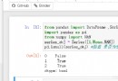
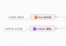
復制代碼First use merge/切割實體,Put the previous two instances(instance)合並成一個實例,命名為UDcomp. 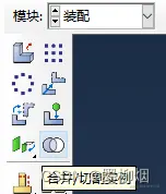
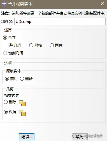
a.InstanceFromBooleanMerge(name='UDcomp', instances=(a.instances['fiber-1'],
a.instances['matrix-1'], ), keepIntersections=ON,
originalInstances=SUPPRESS, domain=GEOMETRY)
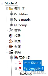
復制代碼A part is automatically generated under the model,接下來雙擊UDcomp部件,Use the cut command,Draw two rectangles,Do a stretch cut. 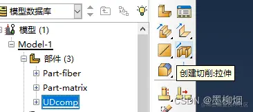
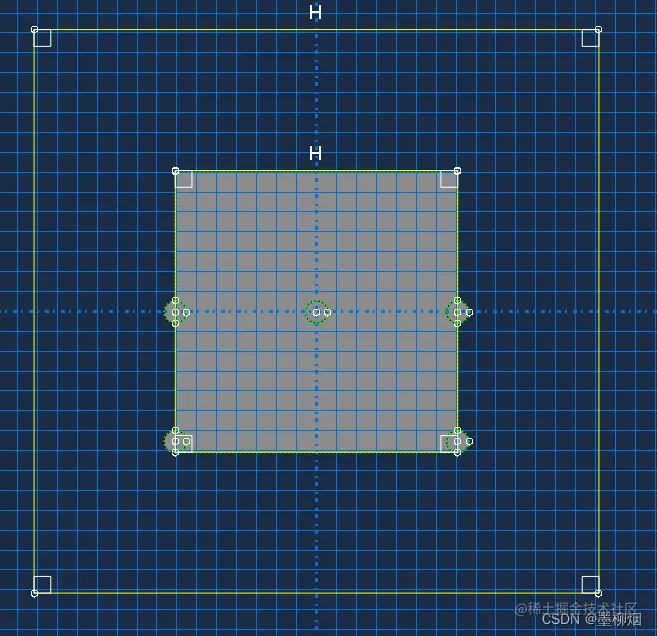 result after cutting:
# Select MergeUDcompfront and right,The plane on which to make the cut sketch.
p = mdb.models['Model-1'].parts['UDcomp']
f, e = p.faces, p.edges
t = p.MakeSketchTransform(sketchPlane=f[23], sketchUpEdge=e[44],
sketchPlaneSide=SIDE1, sketchOrientation=RIGHT, origin=(25.0, 25,
5.0))
# 草圖sConvert the generated location as above
s = mdb.models['Model-1'].ConstrainedSketch(name='__profile__',
sheetSize=141.42, gridSpacing=3.53, transform=t)
# The following sentence is based on guesswork,for parts according tosSketch projection
p.projectReferencesOntoSketch(sketch=s, filter=COPLANAR_EDGES)
# Draw two rectangles, one large and one small,Used for cutting
s.rectangle(point1=(-25.0, -25.0), point2=(25.0, 25.0))
s.rectangle(point1=(-35, -35), point2=(35, 35))
p.CutExtrude(sketchPlane=f[23], sketchUpEdge=e[44], sketchPlaneSide=SIDE1,
sketchOrientation=RIGHT, sketch=s, flipExtrudeDirection=OFF)
del mdb.models['Model-1'].sketches['__profile__']
復制代碼比較基礎,GUIThe steps are not shown 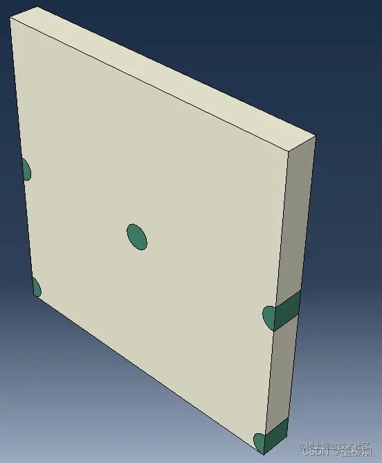
mdb.models['Model-1'].Material(name='matrix')
mdb.models['Model-1'].materials['matrix'].Elastic(table=((50.0, 0.3), ))
mdb.models['Model-1'].Material(name='fiber')
mdb.models['Model-1'].materials['fiber'].Elastic(table=((273.0, 0.2), ))
mdb.models['Model-1'].HomogeneousSolidSection(name='Section-matrix',
material='matrix', thickness=None)
mdb.models['Model-1'].HomogeneousSolidSection(name='Section-fiber',
material='fiber', thickness=None)
p = mdb.models['Model-1'].parts['UDcomp']
c = p.cells
cells = c.getSequenceFromMask(mask=('[#20 ]', ), )
region = regionToolset.Region(cells=cells)
p.SectionAssignment(region=region, sectionName='Section-matrix', offset=0.0,
offsetType=MIDDLE_SURFACE, offsetField='',
thicknessAssignment=FROM_SECTION)
cells = c.getSequenceFromMask(mask=('[#1f ]', ), )
region = regionToolset.Region(cells=cells)
p.SectionAssignment(region=region, sectionName='Section-fiber', offset=0.0,
offsetType=MIDDLE_SURFACE, offsetField='',
thicknessAssignment=FROM_SECTION)
復制代碼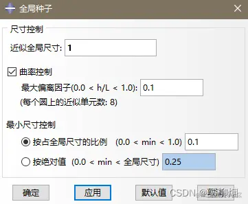
p = mdb.models['Model-1'].parts['UDcomp']
c = p.cells
cells = c.getSequenceFromMask(mask=('[#1f ]', ), )
region = regionToolset.Region(cells=cells)
p.SectionAssignment(region=region, sectionName='Section-fiber', offset=0.0,
offsetType=MIDDLE_SURFACE, offsetField='',
thicknessAssignment=FROM_SECTION)
p.seedPart(size=1.0, deviationFactor=0.1, minSizeFactor=0.1)
p = mdb.models['Model-1'].parts['UDcomp']
c = p.cells
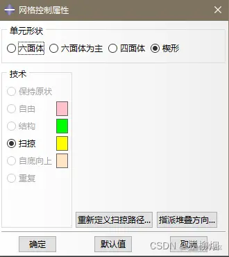
pickedRegions = c.getSequenceFromMask(mask=('[#3f ]', ), )
p.setMeshControls(regions=pickedRegions, elemShape=WEDGE)
p = mdb.models['Model-1'].parts['UDcomp']
p.generateMesh()
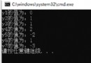
復制代碼First delete the instances of the two red crosses,否則會報錯 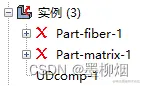
 最後成功運行
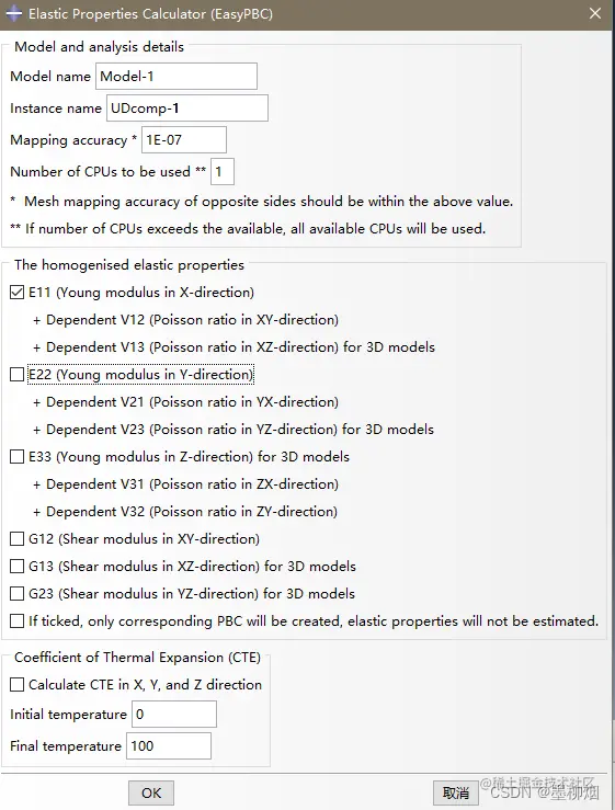
This article learns again through a simple caseabaqus代碼,A new cutting command has been added compared to the previous ones,Thereby satisfying the periodic condition. 目前存在的問題:When specifying a sectionGUIThe operation is manual selection,It cannot be reproduced by code alone,Therefore a new way of specifying sections is required,Will be updated in the next article.