Jane Medium : This paper gives MicroPython Kernel Development Notes : Experimental tasks are embedded in the book Medium mem32 Some contents of software use cases .
key word:MicroPython,MM32F3277,mem32
utilize MicroPython One of the groups can directly access MCU Functions of memory ,mem8、mem16、mem32, You can press 4 byte 、2 byte 、1 Bytes access memory space . MCU The control registers corresponding to most functional modules in are distributed in ARM In the kernel storage space , therefore With the help of this set of memory access functions , It can not only bypass MicroPython Kernel pair MCU To operate , Speed up the software , what's more , Can be realized in MicroPython Functions not yet available in the kernel , Or some functions have defects that need to be corrected .
Here are some specific examples to show this application .
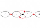
stay MM32F3277 The kernel , There are two Analog comparator :COMP1,COMP2, They are mounted inside APB2 On the bus .
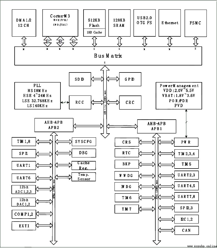
▲ chart 1.1.1 MM32F3277 Internal function module and access bus In the present MicroPython The kernel , Relevant functions of analog comparator are not realized . Can pass mem32 Function to initialize the analog comparator , And read the output state of the comparator .
The analog comparator is mounted on APB2 On the bus , Before use , Need to pass through RCC The controller enables COMP1,COMP2 The clock of .
The following code is through APB2 Register enable Analog comparator clock .
RCC_BASE = const(0x40021000)
APB2ENR = const(RCC_BASE+11*4)
APB1ENR = const(RCC_BASE+12*4)
mem32[APB2ENR] |= 0x8000
according to MM32F3277 Data manual , Check the internal function definition of the controller corresponding to the analog comparator . The details are shown in the following figure .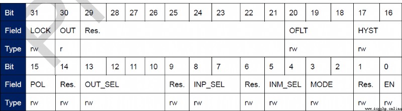
▲ chart 1.1.2 Control register of analog comparator By changing the register setting , You can select the input pin of the analog comparator , Output pins , And working mode . For details, see MM32F3277 Data manual . Analog comparator output (OUT) Located in the... Of the comparison control register 30 position .
The following code enables COMP1,2.
COMP_BASE = const(0x40014000)
COMP_CSR1 = const(COMP_BASE+0xc)
COMP_CSR2 = const(COMP_BASE+0x10)
COMP_CRV = const(COMP_BASE+0x18)
COMP_POLL1 = const(COMP_BASE+0x1c)
COMP_POLL2 = const(COMP_BASE+0x20)
mem32[COMP_CSR1] |= 0x1
mem32[COMP_CSR2] |= 0x1
According to the above settings , The inputs of the two analog comparators are PA0( Forward input )、PA4( Reverse input ). The output of the two comparators can be viewed through the following code .
print('%08x'%mem32[COMP_CSR1])
print('%08x'%mem32[COMP_CSR2])
Set up PA0 High level , PA4 Low level . Check that the output of the comparator is :
40000001
40000001
You can see in the results 30 Is it 1, Indicates that the comparator output is high .
Set up PA0 Low level ,PA4 High level . Check that the output of the comparator is :
00000001
00000001
The results of the 30 Is it 0, The output of the comparator is low . You can see CSR Medium OUT The position reflects the result of external voltage comparison .
The above gives the passage mem32 Direct access to MCU analog comparator control register , How to realize the work of comparator . You can also further study MM32F3277 Data manual , Develop new ways to use analog comparators .
At present MicroPython in PWM Function implementation , There is a drawback , That's it PWM There will be relatively large errors in frequency accuracy . The reason is PWM Timer ARR Be fixed in 999, Timer CNT The count range for is 0 ~ 999. By setting PWM Of duty The number , You can make PWM The change accuracy of the duty cycle of is 1/1000. But it also brings PWM There is a large error between the spectrum and the set frequency .
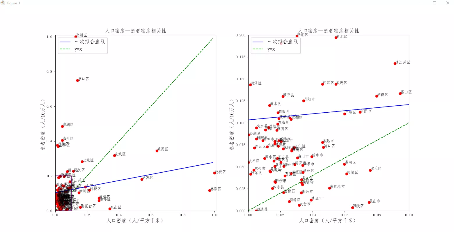
The following figure shows the settings PWM Frequency from 500 To 2000Hz Change between , Actually measure the frequency of the output signal through the external frequency meter , The absolute error between them varies with the set frequency . Especially when the setting frequency is higher , The greater the possible error .
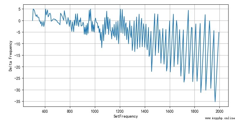
▲ chart 1.2.1 PWM The change of signal frequency error with the frequency setting value The error is caused by PWM The allocation counter in the timer can only take an integer . Suppose the working frequency of the single chip timer comes from MCU Main frequency , The corresponding frequency is f o s c = 120 M H z f_{osc} = 120MHz fosc=120MHz . about A R R = 999 ARR = 999 ARR=999 ,PWM The frequency of is determined by TIM3/TIM4 The value of the prescaler counter determines . f P W M = f o s c ( 1 + P S C ) ⋅ ( A R R + 1 ) f_{PWM} = { {f_{osc} } \over {\left( {1 + PSC} \right) \cdot \left( {ARR + 1} \right)}} fPWM=(1+PSC)⋅(ARR+1)fosc because PSC Must be an integer , So the corresponding output f P W M f_{PWM} fPWM There will be some errors .
If it is aimed at PWM Frequency error , Adjust at the same time ARR The value of , So that it can compensate for PSC The error caused by rounding . The following code makes use of mem32 Function directly to ARR Make changes , Make it compensate for frequency error .
#------------------------------------------------------------
from micropython import const
APB1PERIPH_BASE = const(0x40000000)
TIM3_BASE = const(APB1PERIPH_BASE + 0x0400)
TIM4_BASE = const(APB1PERIPH_BASE + 0x0800)
TIM_TYPE_CR1 = const(0*4)
TIM_TYPE_CR2 = const(1*4)
TIM_TYPE_SR = const(4*4)
TIM_TYPE_CNT = const(9*4)
TIM_TYPE_PSC = const(10*4)
TIM_TYPE_ARR = const(11*4)
TIM_TYPE_CCR1 = const(13*4)
TIM_TYPE_CCR2 = const(14*4)
TIM_TYPE_CCR3 = const(15*4)
TIM_TYPE_CCR4 = const(16*4)
def pwmFreq(f, pwm):
fosc = 96e6
psc = int(fosc/f/1000) - 1
arr = int(fosc/(1+psc)/f) - 1
if pwm < 4: base = TIM3_BASE
else: base = TIM4_BASE
mem32[base+TIM_TYPE_PSC] = psc
mem32[base+TIM_TYPE_ARR] = arr
return arr
After actual measurement ,PWM The error between the output frequency of and the set frequency is basically 0.1% about , This greatly improves PWM Frequency accuracy .
This paper gives MicroPython Kernel Development Notes : Experimental tasks are embedded in the book Medium mem32 Some contents of software use cases .
■ Links to related literature :
● Related chart Links :